
Stations Receivers and Sources
Positioning nomenclature for 2D seismic surveying and processing is based on receiver (REC) stations (STN). Source (SOU) positions are relative to these and can have an offset and skid. Offset is the separation between the REC line and SOU line; this occurs when the receivers are placed to one side of the survey so that the source can move along the survey line without damaging any of the recording equipment. Skid is when the source is displaced along the survey line such that the shot point is positioned in between two receiver stations. Example; for a 4 m receiver separated survey using an Accelerated Weight Drop shooting between every receiver, the source will have a 1 m offset and 2 m skid. This is graphically shown below in Figure 1.
The survey line should be Marked out as in Figure 2 with a 4 numeral STN number on each peg. The first numeral represents the Line number and the following 3 numbers are sequential starting with the first STN at the start of the line (SOL).
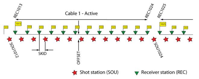
Figure 1. Schematic showing the offset of source and receiver lines and skid of sources with respect to the receivers
File nomenclature
File naming of shot records should be descriptive of where the shot was taken. As current survey design requires multiple spreads with repeated shot stations and reverse shooting; the following 8 character File Name is suggested;
Area – first two characters; (e.g. B1, B2)
Spread – third Character; (a, b, c, d…)
Forward/Reverse shooting – fourth character; (F or R)
Line and SHT number – last 4 characters (2008 = Line 2 shot 8)
e.g. B2aF3012.sg2 is shot 12, on line 3, spread a) Area B2, and shot in the Forward direction.
Seismic line preparation and marking
Positioning, marking and laying out of the seismic line should be in accordance with standard seismic station nomenclature defined above.
| Task | Procedure | |
| 1 | Prepare survey line |
Use GPS to
|
| 2 | Mark stations |
Use a survey chain or rope with knots spaced 2 m apart to mark out 2 or 4 meter stations (STN). Suggest survey rope with 22 x 2 m markings
|
| 3 | Prepare geophone positions |
**The geophones and receiver lines can now be laid out whilst a team prepares the shot pads**
|
| 4 | Prepare shot pads |
|
| 5 | Lay receiver line |
Geophones should be placed at all STN for the first spread (STN 1013 to 1036)
|
| 6 | CHECK STN MARKERS |
Prior to the start of data collection, the GEOPHYSICIST and / or DANMARE linesman should check all survey markers, geophones and shot STN are correct for each shooting pattern (spread).
The survey set up should then be described and recorded on the field data sheet
e.g. LINE 1, 24 channels, 4 m spacing, FAS = 13, LAS = 36, FSS = 0.5, LSS = 48.5.
|
| 7 | Total Station surveying |
All geophone stations and shot locations need to be accurately surveyed due to the extreme topographical variations.
|
Equipment recommendations
MU recommendations;
- Deployment of a larger number of channels to achieve greater offsets as higher offsets have better S/N ratio
- Acquire new cables (water proof) and more geophones.
- Extra cables and geophones for deploying at least one spread ahead of acquisition.
Geophones and takeout cables with water proof screw thread connectors (Photo 1) can be manufactured from an Indian cable supplier (http://www). An accurate wiring diagram and parts list will need to be drawn up to commission the work.
As the GEODE is a modular system, any number of GEODE 24 seismographs can be added to extend the channel count. Recommend to expand the current system immediately to 48 and up to 96 channels in the future. Currently available second hand, are two GEODE 24 seismographs.
Current equipment modification suggestions;
- Accelerated Weight Drop (AWD) pull release rope needs to be replaced. Currently very thin (but strong) and digs into operators hand during pulling. Could have simple garden hose or some handle introduced.
- AWD is difficult to manoeuvre/manhandle from place to place especially in steep wet terrain. Suggestions;
- Wrap legs and mast with high density foam to pad shoulders whilst carrying
- More crew
- Carry handles
- AWD - wire rope got caught 3-4 times between the pulley wheel and guard - the cable is now kinked and needs re-termination or be replaced with an alternative.
- Adjustable legs need to have split pins replaced so legs can be adjusted in the field and lock nuts need to be used on the AWD to prevent self dismantling.
- Striker plate needs a handle so it can be pulled out of the mud and moved easily.
- Field crew need a good set of cutters and multi-meter (one which can test capacitance; nano farads) at the trigger.
- Connections at trigger extension cable and trigger (including spares) should be a water proof (waterproof screw type) set up for only one possible connection polarity. This would allow quick testing and changing of triggers with little/no training.
- Trigger extension break out box should also have the connectors which can only be connected in one way to protect polarity (waterproof screw type). Immediately the –ve polarity banana socket (currently coloured with faded permanent marker pen) should be replaced with the correct black socket.
- Although the GEODE is waterproof a waterproof container (e.g. modified ESKIE) to protect water ingress into the external connectors could be made.
Suggestion from Reddy to make new weight drop and employ two on the survey, shooting in from both sides; Shoot 1, shoot 2 and then move both. This would definitely be useful on spreads with larger channel counts. Also allows continuous shooting if there are any issues with an AWD.
Field Practice and Quality Control Procedures
Seismic operator, at least one weight drop operator and one linesman should be maintained as permanent crew members. They will provide training to any new crew member.
- Geophysicist is to QA/QC during stacking and shot moves and put SHOOTING FIRST. If there are only limited issues with the final stack (e.g. 1 or 2 reversed geophones, poor coupling of 1 or 2 geophones, low SNR ...) the problems should be fixed during the moving of the AWD with co-ordination with the linesman and by increasing stacks at the next position. If the problem reoccurs in the next shot record, the AWD should stand down until the problem is resolved and a new stack acquired.
- Linesman should be responsible for ensuring correct; marking of the line, shot stations are correct and correct any problems with the geophones (poor coupling, reversed channels ...) during recording.
- AWD operator to be responsible for safe operation and moving of AWD, rearming the AWD immediately after each stack and moving the AWD in a timely manner. 48 shot moves per day should be achievable.
- Re-arm the AWD almost immediately (5 seconds) after the shot is acquired. Saving 10 - 30 seconds each stack can considerably increase production.
- During the period of rearming the AWD the Geophysicist is to examine the stack and confirm its quality. If necessary (excessive noise, miss-fire ...) then the data should be saved and a new record collected. Saving and clearing data half way through stacking is better than at the end of the stack. Keep all data and document shots which have been shot twice.
- If the operator is uncertain of the signal strength (depth of penetration) it is necessary to conduct tests before production or possibly even during line production if the ground conditions change considerably. Tests should include stacks for 4, 6, 8, and 12 stacks.
- Program the GEODE to record 12 stacks and show every stack;
- Carefully monitor the improvement in the shot record as stacks are required;
- At some point visually there will be no improvement in the shot record as more stacks are acquired. This is the minimum stack count which should be used.
- First weight drop thump should not be recorded as it is used only to compress the ground (inelastic effect). The crew members operating AWD should do that as soon as the AWD is erected. When the AWD is mounted and ready for the first shot the operator should be notified immediately.
- While recording is in progress, two or more people are preparing the shot pads (remove the soft layer until firm flat ground is obtained), marking out and preparing the next geophone spread (removing soft root and soil mass) to avoid any delay.
- Have at least one full spread positioned ahead of the active spread. That will enable continuous recording rather than current lengthy breaks in acquisition.
- Geophones need to be;
- Planted vertically;
- Pressed all the way into the ground with the heal of a boot until the geophone is flush with ground surface;
- Check geophone coupling by gently pulling on the geophone string or trying to move geophone by hand left and right. If it comes out, re-plant it in a better place.
- Positioning errors have to be kept below 1/8 of the geophone or shot separation.
Four Spread shooting and stack tables.
The minimum number of stacks at different offsets should be maintained as per the tables below. In poor SNR areas stacks should be increased as per the QC procedure.
FILE can be 1001, 1002... if the GEODE does not allow Alpha-numeric file masks (e.g. B2aF)
table 1. Shooting and stack tables for spreads 1 and 2 forward then reverse shooting
SPREAD 1: FAS 13, LAS 36, FSS 1001, LSS1048
| SPREAD 2: FAS 25, LAS 48, FSS 1013, LSS1060 | ||||||
| STN | SHOT # | FILE | STACKS | STN | SHOT # | FILE | STACKS |
| 1 | 1 | B2aF1001 | 8 | 60 | 49 | B2bR1049 | 8 |
| 2 | 2 | B2aF1002 | 8 | 59 | 50 | B2bR1050 | 8 |
| 3 | 3 | B2aF1003 | 8 | 58 | 51 | B2bR1051 | 8 |
| 4 | 4 | B2aF1004 | 8 | 57 | 52 | B2bR1052 | 8 |
| 5 | 5 | B2aF1005 | 8 | 56 | 53 | B2bR1053 | 8 |
| 6 | 6 | B2aF1006 | 7 | 55 | 54 | B2bR1054 | 7 |
| 7 | 7 | B2aF1007 | 7 | 54 | 55 | B2bR1055 | 7 |
| 8 | 8 | B2aF1008 | 7 | 53 | 56 | B2bR1056 | 7 |
| 9 | 9 | B2aF1009 | 7 | 52 | 57 | B2bR1057 | 7 |
| 10 | 10 | B2aF1010 | 7 | 51 | 58 | B2bR1058 | 7 |
| 11 | 11 | B2aF1011 | 6 | 50 | 59 | B2bR1059 | 6 |
| 12 | 12 | B2aF1012 | 6 | 49 | 60 | B2bR1060 | 6 |
| 13 | 13 | B2aF1013 | 6 | 48 | 61 | B2bR1061 | 6 |
| 14 | 14 | B2aF1014 | 6 | 47 | 62 | B2bR1062 | 6 |
| 15 | 15 | B2aF1015 | 6 | 46 | 63 | B2bR1063 | 6 |
| 16 | 16 | B2aF1016 | 5 | 45 | 64 | B2bR1064 | 5 |
| 17 | 17 | B2aF1017 | 5 | 44 | 65 | B2bR1065 | 5 |
| 18 | 18 | B2aF1018 | 5 | 43 | 66 | B2bR1066 | 5 |
| 19 | 19 | B2aF1019 | 5 | 42 | 67 | B2bR1067 | 5 |
| 20 | 20 | B2aF1020 | 5 | 41 | 68 | B2bR1068 | 5 |
| 21 | 21 | B2aF1021 | 5 | 40 | 69 | B2bR1069 | 4 |
| 22 | 22 | B2aF1022 | 5 | 39 | 70 | B2bR1070 | 4 |
| 23 | 23 | B2aF1023 | 5 | 38 | 71 | B2bR1071 | 4 |
| 24 | 24 | B2aF1024 | 5 | 37 | 72 | B2bR1072 | 4 |
| 25 | 25 | B2aF1025 | 5 | 36 | 73 | B2bR1073 | 4 |
| 26 | 26 | B2aF1026 | 5 | 35 | 74 | B2bR1074 | 4 |
| 27 | 27 | B2aF1027 | 5 | 34 | 75 | B2bR1075 | 4 |
| 28 | 28 | B2aF1028 | 5 | 33 | 76 | B2bR1076 | 4 |
| 29 | 29 | B2aF1029 | 5 | 32 | 77 | B2bR1077 | 5 |
| 30 | 30 | B2aF1030 | 5 | 31 | 78 | B2bR1078 | 5 |
| 31 | 31 | B2aF1031 | 5 | 30 | 79 | B2bR1079 | 5 |
| 32 | 32 | B2aF1032 | 5 | 29 | 80 | B2bR1080 | 5 |
| 33 | 33 | B2aF1033 | 5 | 28 | 81 | B2bR1081 | 5 |
| 34 | 34 | B2aF1034 | 6 | 27 | 82 | B2bR1082 | 6 |
| 35 | 35 | B2aF1035 | 6 | 26 | 83 | B2bR1083 | 6 |
| 36 | 36 | B2aF1036 | 6 | 25 | 84 | B2bR1084 | 6 |
| 37 | 37 | B2aF1037 | 6 | 24 | 85 | B2bR1085 | 6 |
| 38 | 38 | B2aF1038 | 6 | 23 | 86 | B2bR1086 | 6 |
| 39 | 39 | B2aF1039 | 7 | 22 | 87 | B2bR1087 | 7 |
| 40 | 40 | B2aF1040 | 7 | 21 | 88 | B2bR1088 | 7 |
| 41 | 41 | B2aF1041 | 7 | 20 | 89 | B2bR1089 | 7 |
| 42 | 42 | B2aF1042 | 7 | 19 | 90 | B2bR1090 | 7 |
| 43 | 43 | B2aF1043 | 7 | 18 | 91 | B2bR1091 | 7 |
| 44 | 44 | B2aF1044 | 8 | 17 | 92 | B2bR1092 | 8 |
| 45 | 45 | B2aF1045 | 8 | 16 | 93 | B2bR1093 | 8 |
| 46 | 46 | B2aF1046 | 8 | 15 | 94 | B2bR1094 | 8 |
| 47 | 47 | B2aF1047 | 8 | 14 | 95 | B2bR1095 | 8 |
| 48 | 48 | B2aF1048 | 8 | 13 | 96 | B2bR1096 | 8 |
Tables 2. Shooting and Stack tables for Spreads 3 and 4 forward then reverse shooting
| SPREAD 3: FAS 37, LAS 60, FSS 1025, LSS1072 | SPREAD 4: FAS 49, LAS 72, FSS 1037, LSS1084 | ||||||
| STN | SHOT # | FILE | STACKS | STN | SHOT # | FILE | STACKS |
| 25 | 97 | B2aF1097 | 8 | 84 | 145 | B2bR1145 | 8 |
| 26 | 98 | B2aF1098 | 8 | 83 | 146 | B2bR1146 | 8 |
| 27 | 99 | B2aF1099 | 8 | 82 | 147 | B2bR1147 | 8 |
| 28 | 100 | B2aF1100 | 8 | 81 | 148 | B2bR1148 | 8 |
| 29 | 101 | B2aF1101 | 8 | 80 | 149 | B2bR1149 | 8 |
| 30 | 102 | B2aF1102 | 7 | 79 | 150 | B2bR1150 | 7 |
| 31 | 103 | B2aF1103 | 7 | 78 | 151 | B2bR1151 | 7 |
| 32 | 104 | B2aF1104 | 7 | 77 | 152 | B2bR1152 | 7 |
| 33 | 105 | B2aF1105 | 7 | 76 | 153 | B2bR1153 | 7 |
| 34 | 106 | B2aF1106 | 7 | 75 | 154 | B2bR1154 | 7 |
| 35 | 107 | B2aF1107 | 6 | 74 | 155 | B2bR1155 | 6 |
| 36 | 108 | B2aF1108 | 6 | 73 | 156 | B2bR1156 | 6 |
| 37 | 109 | B2aF1109 | 6 | 72 | 157 | B2bR1157 | 6 |
| 38 | 110 | B2aF1110 | 6 | 71 | 158 | B2bR1158 | 6 |
| 39 | 111 | B2aF1111 | 6 | 70 | 159 | B2bR1159 | 6 |
| 40 | 112 | B2aF1112 | 5 | 69 | 160 | B2bR1160 | 5 |
| 41 | 113 | B2aF1113 | 5 | 68 | 161 | B2bR1161 | 5 |
| 42 | 114 | B2aF1114 | 5 | 67 | 162 | B2bR1162 | 5 |
| 43 | 115 | B2aF1115 | 5 | 66 | 163 | B2bR1163 | 5 |
| 44 | 116 | B2aF1116 | 5 | 65 | 164 | B2bR1164 | 5 |
| 45 | 117 | B2aF1117 | 4 | 64 | 165 | B2bR1165 | 4 |
| 46 | 118 | B2aF1118 | 4 | 63 | 166 | B2bR1166 | 4 |
| 47 | 119 | B2aF1119 | 4 | 62 | 167 | B2bR1167 | 4 |
| 48 | 120 | B2aF1120 | 4 | 61 | 168 | B2bR1168 | 4 |
| 49 | 121 | B2aF1121 | 4 | 60 | 169 | B2bR1169 | 4 |
| 50 | 122 | B2aF1122 | 4 | 59 | 170 | B2bR1170 | 4 |
| 51 | 123 | B2aF1123 | 4 | 58 | 171 | B2bR1171 | 4 |
| 52 | 124 | B2aF1124 | 4 | 57 | 172 | B2bR1172 | 4 |
| 53 | 125 | B2aF1125 | 5 | 56 | 173 | B2bR1173 | 5 |
| 54 | 126 | B2aF1126 | 5 | 55 | 174 | B2bR1174 | 5 |
| 55 | 127 | B2aF1127 | 5 | 54 | 175 | B2bR1175 | 5 |
| 56 | 128 | B2aF1128 | 5 | 53 | 176 | B2bR1176 | 5 |
| 57 | 129 | B2aF1129 | 5 | 52 | 177 | B2bR1177 | 5 |
| 58 | 130 | B2aF1130 | 6 | 51 | 178 | B2bR1178 | 6 |
| 59 | 131 | B2aF1131 | 6 | 50 | 179 | B2bR1179 | 6 |
| 60 | 132 | B2aF1132 | 6 | 49 | 180 | B2bR1180 | 6 |
| 61 | 133 | B2aF1133 | 6 | 48 | 181 | B2bR1181 | 6 |
| 62 | 134 | B2aF1134 | 6 | 47 | 182 | B2bR1182 | 6 |
| 63 | 135 | B2aF1135 | 7 | 46 | 183 | B2bR1183 | 7 |
| 64 | 136 | B2aF1136 | 7 | 45 | 184 | B2bR1184 | 7 |
| 65 | 137 | B2aF1137 | 7 | 44 | 185 | B2bR1185 | 7 |
| 66 | 138 | B2aF1138 | 7 | 43 | 186 | B2bR1186 | 7 |
| 67 | 139 | B2aF1139 | 7 | 42 | 187 | B2bR1187 | 7 |
| 68 | 140 | B2aF1140 | 8 | 41 | 188 | B2bR1188 | 8 |
| 69 | 141 | B2aF1141 | 8 | 40 | 189 | B2bR1189 | 8 |
| 70 | 142 | B2aF1142 | 8 | 39 | 190 | B2bR1190 | 8 |
| 71 | 143 | B2aF1143 | 8 | 38 | 191 | B2bR1191 | 8 |
| 72 | 144 | B2aF1144 | 8 | 37 | 192 | B2bR1192 | 8 |
Observations and daily log
The field observer’s notes must represent everything which went on in the field so issues with data, equipment and procedures can be identified. Observations of the following need to be made:
- Time on site and off site
- Crew numbers and progress rates.
- All data parameters including the location of files
- Quick sketch of spread layout including topography with respect to STN numbers FAS, LAS, FSS and LSS.
- Numbers of stacks and relative noise sources
- Problems /delays caused by equipment e.g. Trigger or AWD issues.


Tidak ada komentar:
Posting Komentar